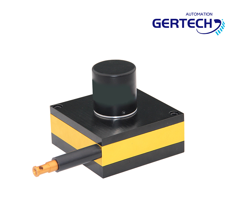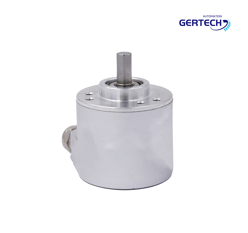
GE-A Series Sine/ Cosine Output Signals Gear Type Encoder
GE-A Series Sine/Cosine Output Signals Encoder
High-precision Speed and Position Sensor with Sine/Cosine Output, Support online debug function
Application:

Spindle - Motor CNC Machine Speed measurement Positioning
n Rotary position and speed sensing in CNC machines
n Energy and power generation systems
n Railway equipment
n Elevators
General Description
The GE-A Gear Type Encoders are non-contact incremental encoders for rotary speed and position measurement. Based on Gertech’s unique Tunneling Magnetoresistance (TMR) sensor technology, they provide orthogonal differential sin/cos signals with high quality, along with an index signal and their inverse signals. The GE-A series are designed for 0.3~1.0-module gears with different teeth numbers.
Features
Output signal amplitude in 1Vpp with high quality
High frequency response up to 1MHz
Operating temperature range from -40°C to 100°C
IP68 protection grade
Advantages
n Fully sealed housing with metal case to ensure the highest protection level
n Non-contact measurement, abrasion and vibration free, can work in harsh environments such as water, oil or dust
n Weak magnetic induction prevents the gear from being magnetized, and the surface of the encoder is not easy to adsorb iron filings
n Large tolerance to air-gap and installation position with high-sensitivity TMR sensors
n Both convex and concave type are allowed for the index teeth
Electrical Parameters
|
SYMBOL |
PARAMETER NAME |
VALUE |
NOTE |
|
Vcc |
Supply Voltage |
5±10%V |
DC |
|
Lout |
Output Current |
≤20mA |
No Load |
|
Vout |
Output Signal |
sin/cos (1Vpp±10%) |
|
|
Fin |
Input Frequency |
≤1M Hz |
|
|
Fout |
Output Frequency |
≤1M Hz |
|
|
|
Phase |
90°±5% |
|
|
|
Calibration Method |
Manual |
|
|
|
Insulation Resistance |
10MΩ |
DC500V |
|
|
Withstand Voltage |
AC500 V |
1 Min |
|
|
EMC Group Pulse |
4000 V |
Mechanical Parameters
|
SYMBOL |
PARAMETER NAME |
VALUE |
NOTE |
|
D |
Distance between Mounting Holes |
27mm |
Using two M4 screws |
|
Gap |
Mounting Air-gap |
0.2/0.3/0.5mm |
Corresponding to 0.4/0.5/0.8- module respectively |
|
Tol |
Mounting Tolerance |
±0.05mm |
|
|
To |
Operating Temperature |
-40~100°C |
|
|
Ts |
Storage Temperature |
-40~100°C |
|
|
P |
Protection Grade |
IP68 |
Zinc alloy housing, Fully potted |
Recommended Gear Parameters
|
SYMBOL |
PARAMETER NAME |
VALUE |
NOTE |
|
M |
Gear Module |
0.3~1.0mm |
|
|
Z |
Number of Teeth |
no limit |
|
|
δ |
Width |
Min.10mm |
Recommend 12mm |
|
|
Material |
ferromagnetic steel |
Recommend 45#steel |
|
|
Index Tooth Shape |
convex /concave tooth |
Recommend concave tooth |
|
|
Tooth Width Ratio between Two Layers |
1:1 |
Width of the index tooth is 6mm |
|
|
Gear Accuracy |
above level ISO8 |
Corresponding to level JIS4 |
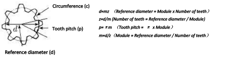
Calculation method of gear parameters:
Output Signals
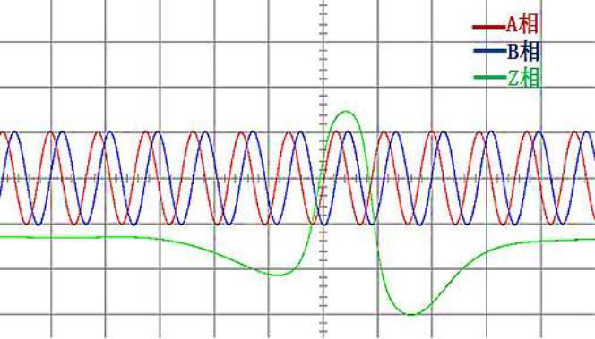
The encoder’s output signals are differential sine/cosine signals with 1Vpp amplitude along with the index signal. There are six output terminals including A+/A-/B+/B-/Z+/Z-. A/B signals are two orthogonal differential sine/cosine signals, and the Z signal is the index signal.
The following chart is the measured A/B/Z differential X-T signals.
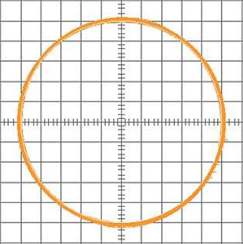
The following chart is the Lissajous-Figure of the measured X-Y signals.
Gear Module
The GE-A product series is designed for gears with 0.3~1.0-module, and the number of teeth may vary.
The following table shows the recommended mounting air-gap under 0.4/0.5/0.8-module.
|
Gear Module |
Mounting Air-gap |
Mounting Tolerance |
|
0.4 |
0.2mm |
±0.05mm |
|
0.5 |
0.3mm |
±0.05mm |
|
0.8 |
0.5mm |
±0.05mm |
Number of Teeth
The encoder should match gears with proper number of teeth for optimal results. The recommended number of teeth is 128, 256, or 512. The minor difference in teeth number is acceptable without affecting the quality of the output signals.
Installation Procedure
The encoder features a compact design with the distance between two mounting holes at 27mm, making it compatible with most of the similar products on the market. The installation procedure is as follows.
1. Mount the encoder using two M4 screws. The screws should not be firmly tightened yet to allow adjustment for the mounting air-gap.
2. Insert a feeler gauge with desired thickness in the middle of the encoder and the gear. Move the encoder toward the gear until there is no space between the encoder, the feeler gauge and the gear, and the feeler can be removed smoothly without apply extra force.
3. Firmly tighten the two M4 screws and pull out the feeler gauge.
Due to the encoder’s built-in self-calibration capability, it will produce desired output signal as long as the proper mounting air-gap is ensured by the above procedure within tolerance.
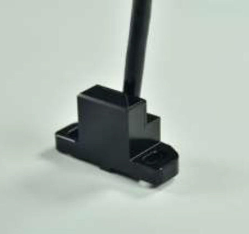
Cable
Normal Version encoder cable consists of eight twisted-pair shielded wires. The cross section of the cable core is 0.14mm2, and the outer diameter is 5.0±0.2mm. The cable length is 1m、3m、5m by default. Enhanced Version encoder cable consists of ten twisted-pair shielded wires. The cross section of the cable core is 0.14mm2 , and the outer diameter is 5.0±0.2mm. The cable length is 1m、3m、5m by default.
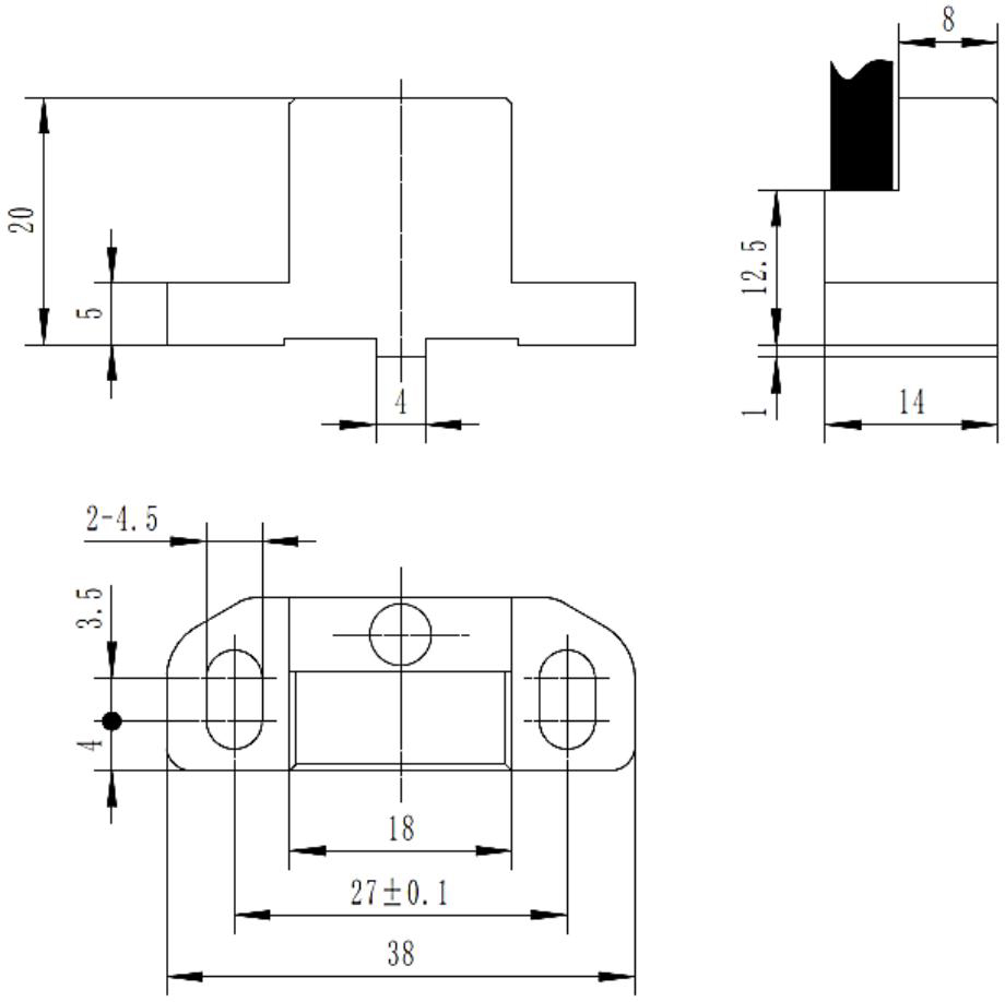
Dimensions
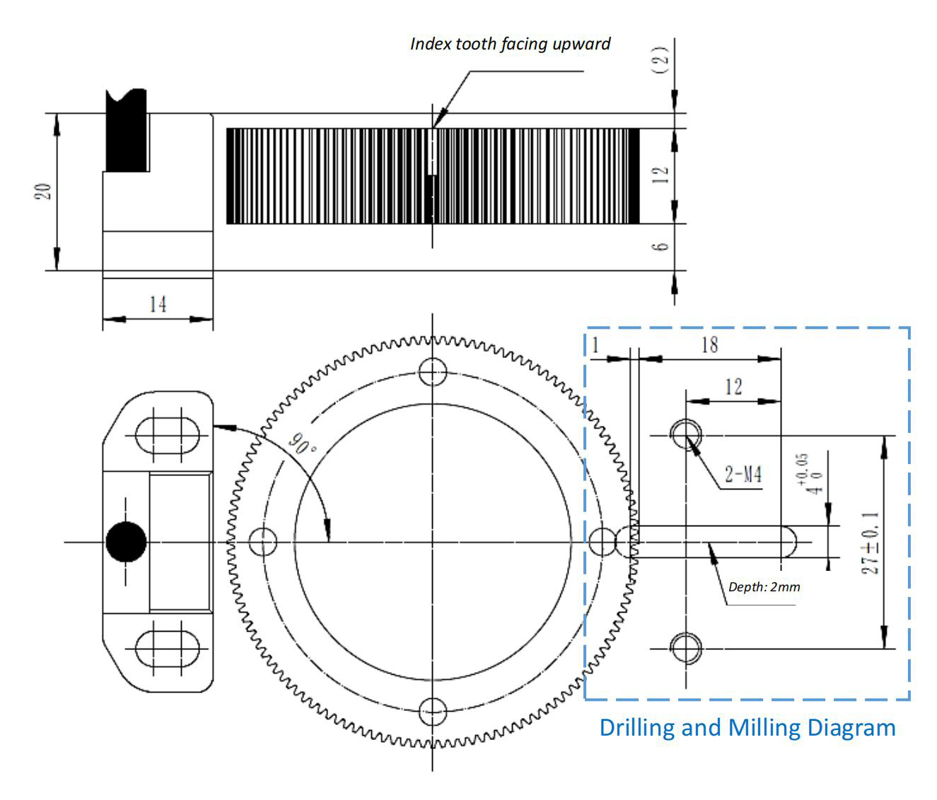
Mounting Position
Order Code
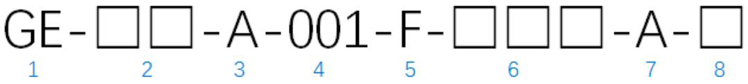
1: Gear Type Encoder
2(Gear Module):04: 0:4-module 05:0:5-module 0X: 0:X module;
3(A:Sin/Cos signals Type): A:Sin/Cos signals;
4(Interpolation):1 (default);
5(Index Shape): F:concave tooth M:convex tooth;
6(Number of Teeth):128,256,512,XXX;
7(Cable Length):1m(standard),3m,5m;
8(Online Debug):1:support, 0: not support;
The information provided herein is believed to be accurate and reliable. Publication neither conveys nor implies any license under patent or other industrial or intellectual property rights. Gertech reserves the right to make changes to product specifications for the purpose of improving product quality, reliability, and functionality. Gertech does not assume any liability arising out of the application and use of its products. Gertecg’s customers using or selling this product for use in appliances, devices, or systems where malfunction can reasonably be expected to result in personal injury do so at their own risk and agree to fully indemnify Gertech for any damages resulting from such applications.